116
JULIANA YORDANOVA, VASIL KOLEV
analyzed for each subject in each condition was
between 40 and 50 for the passive and nontar-
get ERPs, and about 20-23 for the target ERPs.
Data analysis
Prestiniulus EEG power spectral density
For each artifact-free single sweep, the power
spectral density functions were calculated for
the prestimulus epochs (-1000,0 ms) using the
Fast Fourier Transform (FFT), and then aver-
aged separately for each stimulus type. For sta-
tistical evaluation, the mean absolute band
power (X) in the range of 4-7 Hz was log-trans-
formed according to the formula Y = Iogio(X)
to normalize the power distributions (Gasser,
Bacher, & Mocks, 1982; Gasser et al., 1988).
Digital filtering
Averaged and single-sweep ERPs were digital-
ly bandpass filtered in the theta frequency
range (4-7 Hz). To provide a zero phase shift, a
modified linear bandpass filter was used,
whose weights were based on binomial coeffi-
cients (Wastell, 1979). The filter bandwidth was
adjusted to be 5% from the total analyzed fre-
quency band, which was experimentally prov-
en to minimize filtering artifacts. Although in
this study the main emphasis is placed on sin-
gle-sweep parameters, averaged unfiltered and
filtered (4-7 Hz) ERPs were also obtained to
enable comparison with results from the sin-
gle-sweep analysis and with literature data.
Single sweep analysis
Three parameters of the single-sweep theta re-
sponses were analyzed for two time windows,
early (0-300ms) and late (300-600ms): (1)
maximal amplitude, (2) phase-locking, and (3)
amplitude enhancement relative to prestimu-
lus theta activity.
1) The maximal peak-to-peak amplitude of the
single theta responses was measured in each
of the two time windows. The mean value
was calculated for each subject, stimulus
type, and electrode location.
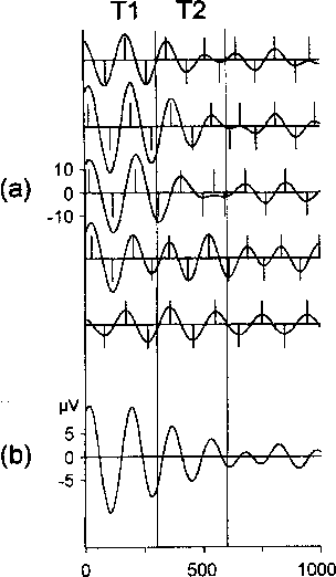
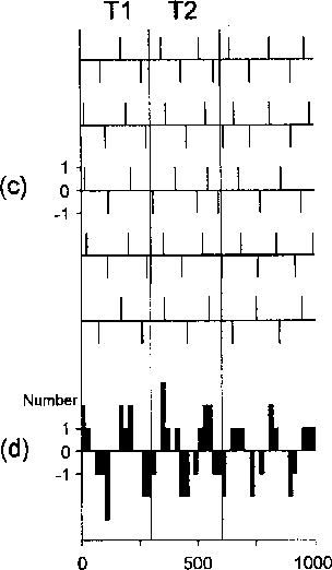
2) For a quantitative evaluation of the phase-
locking, a modification of the single sweep
wave identification (SSWI) method was ap-
plied (Kolev & Daskalova, 1990; Kolev &
Yordanova, 1997). The steps of the analysis
procedure are described below and are il-
lustrated schematically in Figure 1.
First, extrema (minima and maxima) were
identified in the filtered (4-7 Hz) single
sweeps. The amplitudes of the identified extre-
ma were coded with + 1 for the maxima and
with -1 for the minima. Amplitude and latency


TIME (ms)
Figure 1 Single sweep wave identi-
fication (SSWI) method. The left
panel presents (a) five single sweeps
filtered in the theta range (4-7 Hz),
and (b) their averaged waveform.
The wave extrema in the single
sweeps are detected according to
the local maxima and minima,
shown as vertical bars in (a). The
same vertical bars (c) are located at
the corresponding latency positions
without the signals, and (d) the cor-
responding SSWI histogram is built
according to the rule: in consecutive
20 ms time-lags +1 is added to the
histogram bar if the detected extre-
mum in the single sweep is maxi-
mum, or respectively -1, if the de-
tected extremum is minimum. Tl -
time window 0-300 ms, T2 - time
window 300-600 ms.
More intriguing information
1. SAEA EDITOR'S REPORT, FEBRUARY 19882. The name is absent
3. The name is absent
4. Cyber-pharmacies and emerging concerns on marketing drugs Online
5. The name is absent
6. The name is absent
7. Structure and objectives of Austria's foreign direct investment in the four adjacent Central and Eastern European countries Hungary, the Czech Republic, Slovenia and Slovakia
8. THE CHANGING STRUCTURE OF AGRICULTURE
9. The name is absent
10. DISCUSSION: ASSESSING STRUCTURAL CHANGE IN THE DEMAND FOR FOOD COMMODITIES