33

THz transmitter
(fiber-coupled
PC antenna)

H

random
pattern
42cm

6cm
V
÷----
7cm
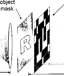
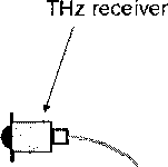
Figure 4.1 : The THz compressive imaging setup. An approximately collimated
beam from the THz transmitter illuminates an object mask and is partially (~50%)
transmitted through a random pattern of opaque pixels. The random patterns, the
focusing lens and the receiver are placed in order to most efficiently focus the THz
beam onto the receiver antenna. One complete time-domain waveform is collected
for each random pattern.
pixels in the image, i.e., M < N2, and can still reconstruct the object perfectly,
through an optimization procedure as described in references [8,9]. The THz Fourier
imaging scheme using CS and phase retrieval in Chapter 3 uses a random subset of
the Fourier basis as rows of Φ. Here, the single-pixel imaging method chooses a set of
vectors, whose entries are randomly picked to be 1 or 0 with equal probability, as rows
of Φ [60]. In other words, for each row in Φ, only a random subset (approximately
half) of the pixels are set to unity (100% transmission), while the remainder are set
to zero (no transmission). Thus, the terahertz beam traveling from the object to the
detector is filtered by randomly blocking a subset of the spatial wave front.
4.2 Imaging experiment
Figure 4.1 illustrates the imaging setup, which consists of a THz transmitter/receiver
pair (fiber-coupled photoconductive antenna), a planar screen with a random pattern
More intriguing information
1. 09-01 "Resources, Rules and International Political Economy: The Politics of Development in the WTO"2. The Impact of Financial Openness on Economic Integration: Evidence from the Europe and the Cis
3. The name is absent
4. The Values and Character Dispositions of 14-16 Year Olds in the Hodge Hill Constituency
5. Sex-gender-sexuality: how sex, gender, and sexuality constellations are constituted in secondary schools
6. Income Growth and Mobility of Rural Households in Kenya: Role of Education and Historical Patterns in Poverty Reduction
7. Implementation of a 3GPP LTE Turbo Decoder Accelerator on GPU
8. Chebyshev polynomial approximation to approximate partial differential equations
9. Accurate and robust image superresolution by neural processing of local image representations
10. Magnetic Resonance Imaging in patients with ICDs and Pacemakers