54

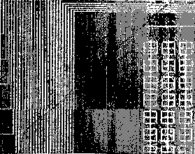
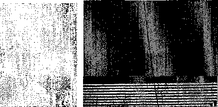
(a) Defect location 1

(c) Defect location 2
(b) Defect location 2

(a) Defect locations on SLM 2
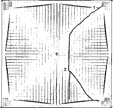
Figure 5.10 : (a) Locations of defects on SLM 2 observed under the microscope
(see lines sketched on mask), (b) An 32×32 image of the modulation depth of the
pixels on SLM 2, overlaid with sketches of defects in (a). At 0.37 THz, the SLM
provides around 20% amplitude modulation at the darker regions on the image, and
has zero modulation at the brighter regions. The defects cut off some SLM pixels
from their Schottky pads, thus the SLM cannot provide any amplitude modulation
at the corresponding pixel locations.
Figure 5.9 : Microscope images of defect locations on SLM 1 indicated on Fig-
ure 5.8(a). Location 1 has a crack whereas location 2 and 3 have fabrication defects.

(b) Modulation depth image of SLM 2
More intriguing information
1. The Triangular Relationship between the Commission, NRAs and National Courts Revisited2. The name is absent
3. Prizes and Patents: Using Market Signals to Provide Incentives for Innovations
4. The Economics of Uncovered Interest Parity Condition for Emerging Markets: A Survey
5. Linkages between research, scholarship and teaching in universities in China
6. Developing vocational practice in the jewelry sector through the incubation of a new ‘project-object’
7. Ongoing Emergence: A Core Concept in Epigenetic Robotics
8. The use of formal education in Denmark 1980-1992
9. The Structure Performance Hypothesis and The Efficient Structure Performance Hypothesis-Revisited: The Case of Agribusiness Commodity and Food Products Truck Carriers in the South
10. The name is absent