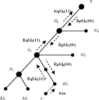
the source is N2 where it is already a BNR, and will update its MFT table entry to add
x’LMR (M3), and unset the S bit in the request message. The request message RqM0(11)
sent to the source to complete the joining process. As mentioned before this message will
arrive in short time to the source because the S bit is set to 0 on the first BNR (N2). The
source upon receiving this registration message sends back a confirmation message
RpM1(00) towards the first BNR(N2) on behalf of x’LMR(M3) request message. At the end
of this procedure the new receiver (x) will be considered as a member in the multicast group.
Again, it is worth to notice that there are no changes in the multicast tree construction
because of this new joining receiver.

|
Nodes |
MFTs | |
|
Before x join |
After x join | |
|
S (Source) |
MTI | IP_V1 |
unchanged |
|
V1 |
MTI | IP_V3 &IP_M4 |
unchanged |
|
V2 |
MTI | IP_V3& IP_M5 MTI | IP_V3 , IP_M3, IP_M5 | |
|
V3 |
MTI | IP_M1 & IP_M2 |
unchanged |
Join message
RqM or RpM
Figure 4.7 Joining process in SReM (Case 2)
■ Case 3:
In this case, the new receiver (x) is the first receiver joining LMR and there is intermediate
IMR(s) in the path to the first BNR towards the source. Figure 4.8 shows this case, where the
new receiver (x) that wants to join the multicast group sends a JoinM message to the
designated LMR (M3). Upon receiving this message, M3 will create and send a RqM1(11)
towards the source. The IMRs along the route to the source just forward this message without
any changes. Upon receiving this message, N2 as the first BNR along the route to the source
updates its MFT entry by adding the x’LMR. Moreover, N1 will update the request message
68
More intriguing information
1. Unilateral Actions the Case of International Environmental Problems2. INTERPERSONAL RELATIONS AND GROUP PROCESSES
3. PROJECTED COSTS FOR SELECTED LOUISIANA VEGETABLE CROPS - 1997 SEASON
4. Reputations, Market Structure, and the Choice of Quality Assurance Systems in the Food Industry
5. CONSIDERATIONS CONCERNING THE ROLE OF ACCOUNTING AS INFORMATIONAL SYSTEM AND ASSISTANCE OF DECISION
6. Cultural Diversity and Human Rights: a propos of a minority educational reform
7. The Distribution of Income of Self-employed, Entrepreneurs and Professions as Revealed from Micro Income Tax Statistics in Germany
8. The name is absent
9. A Study of Adult 'Non-Singers' In Newfoundland
10. The name is absent