141

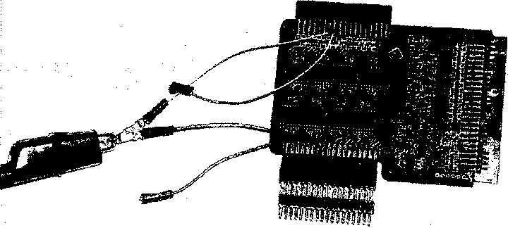
Fig. 4 Wires were soldered the electrode inputs (white) and amplifier outputs
(blue) of channels 14 and 16 to allow the connection of grounding resistors.
Time I
(sec) J
11.1
CM4jtf_SP_res_on_amp
-75
ι□-
CH16_of_SP_res_on_elec
-8.7
11.3-1
CH18_SP_nojjrounding_res I
-7.81
55-
CH14_of_neigh_elec
-3.7
12ЯЙЮ00-
CH14_of_SPjjnfiltered -
-8741COO
1188ШЮ0-

CH16-oΓ-SPjj∏filtered
-114370∞
11858000-
CH16_of_SP_unfiltered
-12294800j

3321-
Statu8-8ignal
-16O9-
3978000-
CH14_of_neigh_unfihered
-2744000


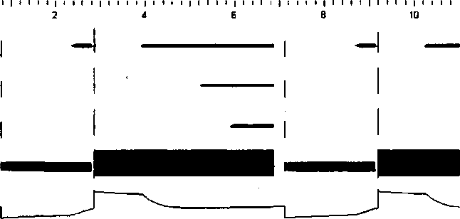
Fig. 5 Here the waveforms are from top to bottom: 1 Channel 14 of the Stim Project. This
channel has a 540kΩ grounding resistor connected in parallel with the amplifier output of the
switching board. 2 Channel 16 of the Stim Project. This channel has a 540kΩ grounding
resistor connected in parallel with the electrode input of the switching board. 3 Channel 18
OftheStim Project. This channel has nogrounding resistors attached. 4 A channel not
connected through the Stim Project recording from the saline medium. 5-7 Unfiltered
outputs of channels 14,16, and 18 showing the large voltages that are the result fluctuations
during switching (note the change in scale, and the correlation between when the voltage
begins to return to baseline and when recording is possible). 8 The status signal, high
indicates the Stim Project is set to stimulate, low indicates recording is selected. 9 Unfiltered
output of the channel not connected to the Stim Project.
More intriguing information
1. The Social Context as a Determinant of Teacher Motivational Strategies in Physical Education2. The Global Dimension to Fiscal Sustainability
3. CREDIT SCORING, LOAN PRICING, AND FARM BUSINESS PERFORMANCE
4. A parametric approach to the estimation of cointegration vectors in panel data
5. The name is absent
6. The name is absent
7. Gender stereotyping and wage discrimination among Italian graduates
8. A MARKOVIAN APPROXIMATED SOLUTION TO A PORTFOLIO MANAGEMENT PROBLEM
9. Does Competition Increase Economic Efficiency in Swedish County Councils?
10. Artificial neural networks as models of stimulus control*