15

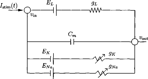
Figure 2.3: Circuit diagram of the Hodgkin-Huxley cell. The voltage v is defined as v ≡ v,n — Vout-
resistors (Na+ and A+). Applying Kirchhoff’s Current Law again yields the following
system of ODEs describing the Hodgkin-HuxIey (HH) model:
Cmv' = -gL{y - El) - gNarn3h(v - ENa) - gκ∏i(υ - Eκ) + 7stim∕A
(2.3)
(2.4)
(2.5)
(2.6)
, rnoo(v) - m
m =---r~∖—
τm(v)
_ ⅛oo(v) - h
ι^h(υ)
l noo(y) - n
n =---rʒ—∙
τn(y)
2.2 The Quasi-Active Isopotential Cell
It is well-known that, while linear models do not reproduce spiking dynamics,
they do provide information about the frequency response of a system. For neuronal
modeling, the linearized systems are good at reproducing the nonlinear system’s sub-
More intriguing information
1. Monopolistic Pricing in the Banking Industry: a Dynamic Model2. DEMAND FOR MEAT AND FISH PRODUCTS IN KOREA
3. Staying on the Dole
4. Weather Forecasting for Weather Derivatives
5. Fortschritte bei der Exportorientierung von Dienstleistungsunternehmen
6. TOWARD CULTURAL ONCOLOGY: THE EVOLUTIONARY INFORMATION DYNAMICS OF CANCER
7. The name is absent
8. A novel selective 11b-hydroxysteroid dehydrogenase type 1 inhibitor prevents human adipogenesis
9. IMMIGRATION AND AGRICULTURAL LABOR POLICIES
10. AN EMPIRICAL INVESTIGATION OF THE PRODUCTION EFFECTS OF ADOPTING GM SEED TECHNOLOGY: THE CASE OF FARMERS IN ARGENTINA