23
Fourier plane

collimating ∣ automated
Ierts ■ translation stage
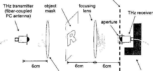
Figure 3.1 : The THz Fourier imaging setup. An approximately collimated beam from
the THz transmitter illuminates an object mask, placed one focal length away from
the focusing lens. The THz receiver raster-scans and samples the Fourier transform
of the object on the focal plane.
3.2 Experimental results
During raster-scanning of the detector in Figure 3.1, an entire time-domain THz
waveform is measured at each detector position. The reconstruction algorithm first
computes the power spectrum of each waveform, selects the spectral amplitude and
phase at a particular wavelength (Λ = 1.5 mm) to obtain a (complex) pixel value,
and assembles a 64 × 64 Fourier image. The following sections demonstrates various
schemes to reconstruct an image of the object from this Fourier data.
3.2.1 Fourier reconstruction with full dataset
Direct 2D Fourier inversion of this image reconstructs the object mask as shown in
Figure 3.2(a). The pixel size is given by ∆,x = ɔʃ, where X is the length in one
dimension of the raster scan area (64 mm) and f is the focal length of the focusing
More intriguing information
1. The name is absent2. Modellgestützte Politikberatung im Naturschutz: Zur „optimalen“ Flächennutzung in der Agrarlandschaft des Biosphärenreservates „Mittlere Elbe“
3. Determinants of Household Health Expenditure: Case of Urban Orissa
4. Migration and employment status during the turbulent nineties in Sweden
5. Iconic memory or icon?
6. The name is absent
7. Imputing Dairy Producers' Quota Discount Rate Using the Individual Export Milk Program in Quebec
8. The name is absent
9. The name is absent
10. The name is absent