116

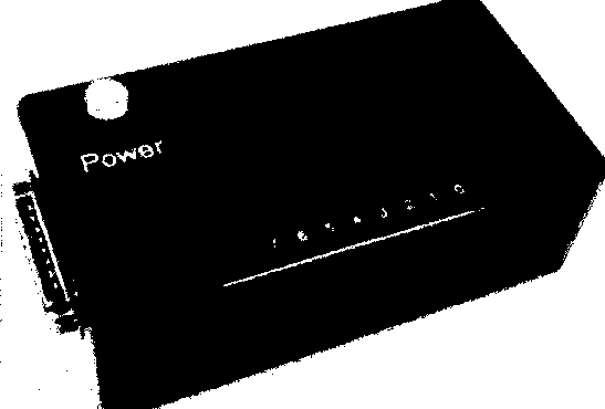
Figure 1 The TlVIS control box. The LEDs on the face of the box are used to show the contents of the
output latches, which is very useful during debugging.

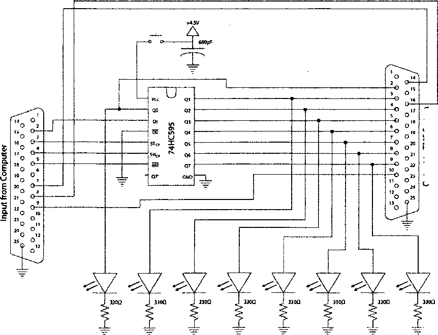
Output toTMS System
Figure 2 Schematic for the TlVIS control box. The output is also a DB25 connector, a DB25 to Centronics
36 cable was constructed to connect the control box to the TIVIS system.
More intriguing information
1. SLA RESEARCH ON SELF-DIRECTION: THEORETICAL AND PRACTICAL ISSUES2. The name is absent
3. Concerns for Equity and the Optimal Co-Payments for Publicly Provided Health Care
4. Secondary school teachers’ attitudes towards and beliefs about ability grouping
5. The name is absent
6. Are class size differences related to pupils’ educational progress and classroom processes? Findings from the Institute of Education Class Size Study of children aged 5-7 Years
7. Should Local Public Employment Services be Merged with the Local Social Benefit Administrations?
8. The name is absent
9. Investment and Interest Rate Policy in the Open Economy
10. The ultimate determinants of central bank independence