switching over to another independent WARP instruction on a
stall.
Computation throughput can still become I/O limited if mem-
ory bandwidth is low. Fortunately, fast on-chip resources, such
as registers, shared memory and constant memory, can be used
in place of off-chip device memory to keep the computation
throughput high. Shared memory is especially useful. It can
reduce memory access time by keeping data on-chip and reduce
redundant calculations by allowing data sharing among indepen-
dent threads. However, shared memory on each SM has 16 access
ports. It takes one cycle if 16 consecutive threads access the same
port (broadcast) or none of the threads access the same port (one
to one). However, a random layout with some broadcast and
some one-to-one accesses will be serialized and cause a stall.
There are several other limitations with shared memory. First,
only threads within a block can share data among themselves
and threads between blocks can not share data through shared
memory. Second, there are only (16KB) of shared memory on
each stream multiprocessor and shared memory is divided among
the concurrent thread blocks on an SM. Using too much shared
memory can reduce the number of concurrent thread blocks
mapped onto an SM.
As a result, it is a challenging task to implement an algorithm
that keeps the GPU cores from idling-we need to partition the
workload across cores, while effectively using shared memory,
and ensuring a sufficient number of concurrently executing thread
blocks.
III. MAP decoding algorithm
The principle of Turbo decoding is based on the BCJR or MAP
(maximum a posteriori) algorithms [15]. The structure of a MAP
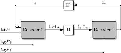
decoder is shown in Figure 1. One iteration of the decoding
process consists of one pass through both decoders. Although
both decoders perform the same set of computations, the two
decoders have different inputs. The inputs of the first decoder
are the deinterleaved extrinsic log-likelihood ratios (LLRs) from
the second decoder and the input LLRs from the channel. The
inputs of the second decoder are the interleaved extrinsic LLRs
from the first decoder and the input LLRs from the channel.

Fig. 1: Overview of turbo decoding
To decode a codeword with N information bits, each decoder
performs a forward traversal followed by a backward traversal
through an N -stage trellis to compute an extrinsic LLR for each
bit. The trellis structure, or the connections between two stages
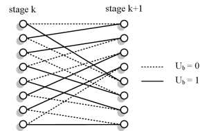
of the trellis, is defined by the encoder. Figure 2 shows the trellis
structure for the 3GPP LTE turbo code, where each state has two
incoming paths, one path for ub =0 and one path for ub =1.
Let sk be a state at stage k, the branch metric (or transition
probability) is defined as:
γk(sk-1,sk)=(Lc(yks)+La(yks))uk +Lc(ykp)pk, (1)
where uk, the information bit, and pk, the parity bit, are de-
pendent on the path taken (sk+1, sk). Lc(yks) is the systematic
channel LLR, La(yks ) is the a priori LLR, and Lc(ykp) is the
parity bit channel LLR at stage k. The decoder first performs

Fig. 2: 3GPP LTE turbo code trellis with 8 states
a forward traversal to compute αk, the forward state metrics for
the trellis state in stage k. The state metrics αk are computed
recursively as the computation depends on αk-1. The forward
state metric for a state sk at stage k, αk (sk), is defined as:
αk(Sk) = max*h- 1 ∈k(ak-ɪ(Sk-ɪ) + γ(Sk-ɪ, Sk)), (2)
where K is the set of paths that connect a state in stage k - 1
to state Sk in stage k.
After the decoder performs a forward traversal, the decoder
performs a backward traversal to compute βk, the backward state
metrics for the trellis state in stage k. The backward state metric
for state Sk at stage k, βk (Sk ), is defined as:
βk ( Sk ) = max *k+1 ∈k ( βk+ι ( Sk+ι ) + γ ( Sk+ι ,Sk )). (3)
Although the computation is the same as the computation for
αk , the state transitions are different. In this case, K is the set
of paths that connect a state in stage k +1 to state Sk in stage
k.
After computing βk , the state metrics for all states in stage k,
we compute two LLRs per trellis state. We compute one state
LLR per state Sk , Λ(Sk |uk =0), for the incoming path that is
connected to state Sk which corresponds to uk =0. In addition,
we also compute one state LLR per state Sk, Λ(Sk∖ub = 1), for
the incoming path that is connected to state Sk which corresponds
to uk =1. The state LLR, Λ(Sk |ub =0), is defined as:
Λ( Sk ∖ub = 0) = ak-1( Sk-1 ) + γ ( Sk-1 ,Sk ) + βk ( Sk ), (4)
where the path from Sk-1 to Sk with ub =0is used in the
computation. Similarly, the state LLR, Λ(Sk∖ub =1), is defined
as:
Λ(Sk∖ub = 1) = ak-1(Sk-1) + γ(Sk-1, Sk) + βk(Sk), (5)
where the path from Sk-1 to Sk with ub =1is used in the
computation.
193
More intriguing information
1. The name is absent2. Strengthening civil society from the outside? Donor driven consultation and participation processes in Poverty Reduction Strategies (PRSP): the Bolivian case
3. HACCP AND MEAT AND POULTRY INSPECTION
4. Problems of operationalizing the concept of a cost-of-living index
5. On the origin of the cumulative semantic inhibition effect
6. Keystone sector methodology:network analysis comparative study
7. The name is absent
8. Monetary Policy News and Exchange Rate Responses: Do Only Surprises Matter?
9. The name is absent
10. A Classical Probabilistic Computer Model of Consciousness