44

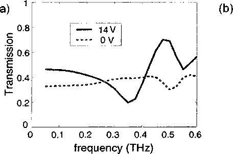
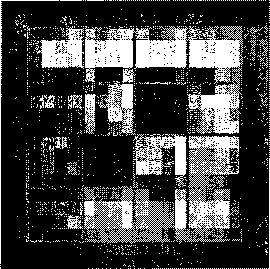
Figure 5.2 : (a) THz amplitude transmission spectra for one of the 16 pixels of the THz
SLM without voltage bias (dashed) and with 14V bias (solid). A large modulation
depth is observed at 0.36 THz, the design resonant frequency, (b) A transmission
image of the 4-by-4 array at 0.36 THz, with two pixels turned off (biased), and the
rest turned on (zero bias).

of pixel groups at high speed.
5.3.1 Modulation depth
This experiment raster-scans the THz receiver across the beam, after it has passed
through the modulator. The substrate lens of the receiver antenna is covered by a
metal mask with a 1-mm aperture to improve the spatial resolution of the measure-
ment. At each receiver position, THz waveform acquisition uses an optical chopper
in the THz beam and a lock-in amplifier to filter the signal from the photoconductive
antenna. Figure 5.2(a) shows the typical transmission spectra for one of the 16 pixels
in the “on” and “off” configurations, i.e., under a de bias voltage of 0 or 14 volts,
respectively. Observed for all 16 pixels is an amplitude modulation depth between
35% and 50% at the design resonant frequency of 0.36 THz. Shown in Figure 5.2(b)
is the transmission image of the 4-by-4 modulator array at 0.36 THz, with two pixels
More intriguing information
1. Strategic Effects and Incentives in Multi-issue Bargaining Games2. Popular Conceptions of Nationhood in Old and New European
3. Pass-through of external shocks along the pricing chain: A panel estimation approach for the euro area
4. Restructuring of industrial economies in countries in transition: Experience of Ukraine
5. Momentum in Australian Stock Returns: An Update
6. The name is absent
7. BILL 187 - THE AGRICULTURAL EMPLOYEES PROTECTION ACT: A SPECIAL REPORT
8. Are combination forecasts of S&P 500 volatility statistically superior?
9. Macro-regional evaluation of the Structural Funds using the HERMIN modelling framework
10. WP 48 - Population ageing in the Netherlands: Demographic and financial arguments for a balanced approach