47

Screen Position (mm)
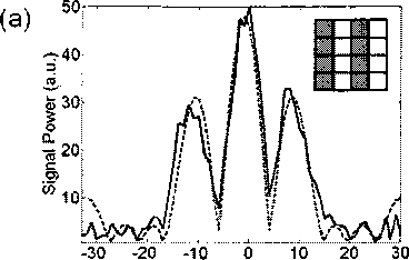
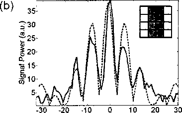
Figure 5.4 : Measured (solid curves) differential fringe patterns produced by the
transmission of the THz beam through the THz SLM in two double-slit Conhgurations,
compared with analytical calculations (dashed curves). The insets show the “on” and
“off” Conhgurations of the 16 pixels, with zero bias on the gray pixels, and the white
pixels modulated with a 3-kHz square signal alternating between 0 and 14V.

Screen Position (mm)
are unbiased. After focusing the transmitted THz wave front with a lens, the THz
detector (with a 1 mm aperture) scans along a line in the focal plane of the lens,
across a 64 mm interval. Figure 5.4 shows the measured differential fringe patterns
(solid curves) at 0.36 THz for the two double-slit configurations. These have the same
slit sizes (b = 4 mm) but different slit separations (α = 8 mm and 12 mm respectively
in Figure 5.4 (a) and (b). As expected, the fringes appear at distances, multiples
of ʌɔ away from the central fringe. Here, Λ is the observation wavelength, f is the
focal length of the focusing lens and α is the slit separation. Analytical calculations
of the double-slit diffraction pattern, assuming a plane wave illumination, best fit the
measured data with а = 9.8 mm and 13.8 mm respectively for the two configurations,
and b = 5 mm (see dashed curves in Figure 5.4). When using metal slits of the same
dimensions as those of the slits formed by the modulator in a direct observation of the
diffraction fringes, similar values for these fit parameters are observed. This indicates
that the differences between the fit parameters and the actual geometrical dimensions
More intriguing information
1. PERFORMANCE PREMISES FOR HUMAN RESOURCES FROM PUBLIC HEALTH ORGANIZATIONS IN ROMANIA2. Spatial patterns in intermunicipal Danish commuting
3. STIMULATING COOPERATION AMONG FARMERS IN A POST-SOCIALIST ECONOMY: LESSONS FROM A PUBLIC-PRIVATE MARKETING PARTNERSHIP IN POLAND
4. Improvements in medical care and technology and reductions in traffic-related fatalities in Great Britain
5. Managing Human Resources in Higher Education: The Implications of a Diversifying Workforce
6. The name is absent
7. The name is absent
8. Economic Evaluation of Positron Emission Tomography (PET) in Non Small Cell Lung Cancer (NSCLC), CHERE Working Paper 2007/6
9. The WTO and the Cartagena Protocol: International Policy Coordination or Conflict?
10. The name is absent