KETONEN et al. : PERFORMANCE-COMPLEXITY COMPARISON OF RECEIVERS FOR A LTE MIMO-OFDM SYSTEM
3363

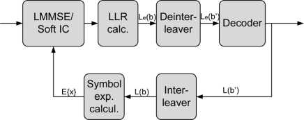
Fig. 4. The soft IC receiver.
TABLE I
Simulation Parameters

TABLE II
Channel Model Parameters
layer, which is then decoded. The layer detected in the first iter-
ation is not updated during the second iteration.
The weight matrix is calculated with the LMMSE algorithm
W = (HhH + <72Im)^1Hh (10)
where H is the channel matrix, σ2 is the noise variance, ( ∙ )h is
the complex conjugate transpose and I ∏ is a F x .U identity
matrix. The layer for detection is chosen according to the post-
detection SNR and the corresponding nulling vector is chosen
from the weight matrix W [4]. All the weight matrices in an
OFDM symbol are calculated and the layer to be detected is
chosen according to the average over all the subcarriers.
After the first iteration, the cancelled symbol expectation is
used to update the weight matrix. The weight matrix on the
second iteration is calculated as
+ Hfe (I - (WW*)⅛ + σ2lM))^1 h⅛ (11)
where h⅛ is the Æth vector from matrix H, & is the layer to
be detected, H⅛ is matrix H with the vectors from previously
detected layers removed and E{x} is the symbol expectation.
The LLRs can be calculated from the LMMSE equalizer out-
puts z as presented in [25] by using an approximate log-like-
lihood criterion. Instead of calculating the Euclidean distance
between the LMMSE equalizer output and the possible trans-
mitted symbols, Gray labeling of the signal points is exploited.
This reduces the latency and complexity but was shown to have
a minor impact on the performance. The bit-metric approxima-
tions L(bx∣z, W) in [25] are calculated as
p⅛Λ(6λ,z)= min ∖zk-xk∖2- min ⅛-⅛∣2 (12)
⅛fc∈<λ ⅛∈¾λ
where к — [Λ∕QJ+1,Λ, = {j⅛ : 6λ = z} is the subset of
hypersymbols {./■}• for which the Λth bit of label b is a and ρk
is the signal-to-interference-and-noise ratio (SINR) of layer k.
Λ(6λ, z) can be simplified by considering zk in only one quadra-
ture dimension given by Λ.
The detected layer is decoded and symbol expectations from
the soft decoder outputs are calculated as [26]
/1 ∖ Q
E{x} = (j)
Q
^∏(1 + ^,ttanh(LA(M∕2)) (13)
x∕∈Ω i=l
|
Number of paths |
6 |
|
Path delays |
[0...5000] ns |
|
Path power |
[-3...-10] dB |
|
BS antenna spacing |
4 λ |
|
MS antenna spacing |
0.5 λ |
|
BS average angle of departure |
50 o |
|
MS average angle of arrival |
67.5 o |
|
BS azimuth spread |
2 o / 5 o |
|
MS azimuth spread |
35 o___________ |
where La(⅛) are the LLRs of coded bits corresponding to x
and Ьц are bits corresponding to constellation point xi. The
expectation calculation in (13) can be simplified to the form
E{x}re = sgn(ZA(^))5,∣ tanh(LA(δi+2))∣. (14)
The constellation point S is chosen from {1,3,5,7} depending
on the signs of La(⅛+i) and Zj4(⅛+2).
III. Performance Comparisons
The communication system, i.e., the transmission throughput
performance of the SIC detector is compared to that of the
К-best LSD and the LMMSE detectors. The simulation param-
eters are based on the LTE standard [21] and are summarized
in Table I. In the horizontally encoded LTE system, two data
streams are encoded separately and then mapped onto different
layers. The strongest layer can be detected and decoded first
and then cancelled from the remaining layer. In the 4×4
antenna system, each of the two streams are multiplexed onto
two antennas; the first stream is multiplexed onto the first and
second antenna and the second stream onto the third and fourth
antenna. The most recent versions of the 3G LTE specifications
also include the 2 × 2 vertically encoded case, where a single
code word is multiplexed on to two layers. In this scenario,
decoding of the layers cannot be performed separately.
The transmission throughput is calculated as the nom-
inal information transmission rate of information bits times
(1 — FER). A 5-MHz bandwidth was assumed in the simula-
tions. The signal-to-noise ratio (SNR) represents Es∕Nq, where
Jss is the symbol energy. Each SNR point includes transmission
of 1000 frames. Perfect channel state information was assumed
in the receiver. The typical urban (TU) channel [27] with BS
azimuth spread of 2 degrees was applied. The normalized
correlation between the spatial channels is about 0.8. There
are six paths in the channel with the largest delay of 5000 ns.
The base station (BS) antenna separation is 4 λ. Parameters
of the used channel models are shown in Table II. In addition,
a spatially uncorrelated channel was considered as well. The
number of turbo decoder iterations in the simulations was 8.
More intriguing information
1. Commuting in multinodal urban systems: An empirical comparison of three alternative models2. Bargaining Power and Equilibrium Consumption
3. The name is absent
4. Understanding the (relative) fall and rise of construction wages
5. Education Responses to Climate Change and Quality: Two Parts of the Same Agenda?
6. On the Existence of the Moments of the Asymptotic Trace Statistic
7. The economic value of food labels: A lab experiment on safer infant milk formula
8. Return Predictability and Stock Market Crashes in a Simple Rational Expectations Model
9. The name is absent
10. Detecting Multiple Breaks in Financial Market Volatility Dynamics