3366
IEEE TRANSACTIONS ON SIGNAL PROCESSING, VOL. 58, NO. 6, JUNE 2010
TABLE III
The Theoretical Complexity of the Receivers as Numbers of Arithmetic Operations
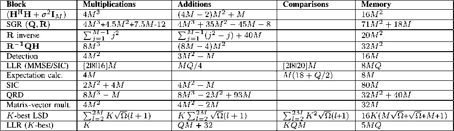
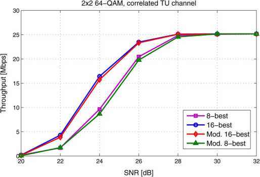
Fig. 9. Data transmission throughput versus SNR in a 2 × 2 system in a highly
correlated channel with the modified tree search.
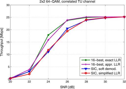
Fig. 10. Data transmission throughput versus SNR in a 2 × 2 system in a highly
correlated channel with the simplified LLR calculation.
close to the hand-coded results with small designs. There can
be more difference with large designs.
The FPGA complexity results are presented in slices, 18-kbit
BRAM and dedicated DSP slices. The DSP slices include
an 18 × 18-bit multiplier. The VHDL from Catapult C was
synthesized to a Xilinx Virtex-4 FPGA with Mentor Graphics
Precision Synthesis. The ASIC results are presented in gate
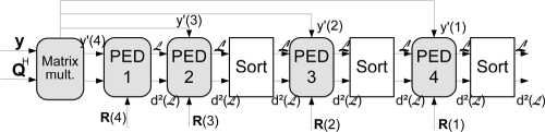
Fig. 11. The top-level architecture of the 2 × 2 K -best LSD.
equivalents (GE) and power consumption estimates. The Syn-
opsys Design Compiler was used in synthesizing the VHDL
along with the UMC 0.18 μm complementary metal oxide
semiconductor (CMOS) technology. The Synopsys Prime-
Power was used for obtaining the statistical activity power
estimates for the implementations.
A. K-BestLSD
The A -bcst LSD receiver includes the QRD block, the
∕√-bcst LSD block and the LLR calculation block. The QR
decomposition block is based on the QRD algorithm from
[30]. Ordering of the channel matrix is not utilized in the
architecture. The top level architecture of the TT-best LSD for
a 2 × 2 antenna system is shown in Fig. 11. The 4×4 antenna
system LSD is based on the same architecture but four more
PED calculation blocks and sorters are added to the design.
The А-best LSD architecture is modified from [20]. A2× 2
and a 4 × 4 antenna system with a real signal model [31] is
assumed. The received signal vector y is multiplied with ma-
trix Q in the matrix multiplication block. Matrix R is mul-
tiplied with the possible transmitted symbols after the QRD
is performed, i.e., when the channel realization changes. Eu-
clidean distances between the last symbol in vector y' and pos-
sible transmitted symbols are calculated in block PED1 in a
2×2 antenna system with d(x2) = ∣∣3∕4 — rfT,4∣∣2. The resulting
lists of symbols and Euclidean distances are not sorted at the
first stage. The distances are added to the Euclidean distances
d(x∣) = 112/3-(/33+/34)112 calculated in the PED2 block. The
lists are sorted and K partial symbol vectors with the smallest
Euclidean distances are kept. PED3 block calculates d(x2) —
llî/2 - (r2,2 ÷ r2,3 ÷ r2,4)l∣2 which are added to the previous
distance and sorted. The last PED block calculates the partial
Euclideandistances c∕(x2) = ∣∣^ — (rɪ 1 ÷∕i^2 ÷r1,3÷r1,4)l∣2.
After adding the previous distances to d(x2), the lists are sorted
More intriguing information
1. Consumption Behaviour in Zambia: The Link to Poverty Alleviation?2. The name is absent
3. The name is absent
4. Mortality study of 18 000 patients treated with omeprazole
5. Trade and Empire, 1700-1870
6. Computational Batik Motif Generation Innovation of Traditi onal Heritage by Fracta l Computation
7. Contribution of Economics to Design of Sustainable Cattle Breeding Programs in Eastern Africa: A Choice Experiment Approach
8. Credit Market Competition and Capital Regulation
9. Sectoral specialisation in the EU a macroeconomic perspective
10. The name is absent