IEEE TRANSACTIONS ON SIGNAL PROCESSING, VOL. 58, NO. 6, JUNE 2010
3368

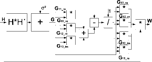
Fig. 13. The top level architecture of the 2 × 2 LMMSE detector.

Fig. 14. The architecture of the symbol expectation calculation.
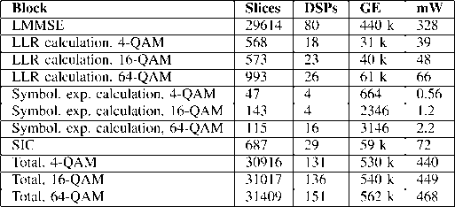
TABLE VII
The 4 × 4 System SIC Receiver Complexity

C. Latency Comparison
The processing latency of a receiver can be expressed as
Drec = Pdet + (Pllr + Ddec)‰ (15)
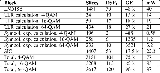
TABLE Vi
The 2 × 2 System SIC Receiver Complexity

LLRs La(⅛) and -J<4(⅛+2) from the decoder. The lookup table
(LUT) is used to find the tan h value.
The complexity of the SIC receiver for a 2 × 2 system is pre-
sented in Table vi. The word lengths were determined with
computer simulations. in symbol expectation and LLR calcu-
lation blocks, the word lengths range from 6 to 16 bits. in the
LMMSE block, word lengths up to 22 bits were used. in addi-
tion, four 18-kbit block RAMs are used to store the channel ma-
trix H and the received symbol vector y and 1 BRAM is used in
the interleaver. The LLR calculation block also includes detec-
tion, i.e., multiplying the received signal with the weight matrix
W. There are two ASIC implementations of the LMMSE block.
The other one is used for the SiC receiver and has a lower la-
tency and higher complexity. The clock frequency in the ASIC
implementation is 100 MHz and from 10 MHz to 95 MHz in
the FpGA implementation.
The complexity of the SIC receiver for a 4 × 4 system is pre-
sented in Table vII. The LMMSE detector is the most complex
part of the receiver taking 9% of the slices and almost 80%
of the gates. Performing a 4 × 4 matrix inversion in 4 clock cy-
cles consumes a large portion of the resources. The LMMSE de-
tector is based on the SGR [32]. The number of BRAMs needed
to store the channel matrix, the weight matrix W and the re-
ceived signal is 11. There are two LLR calculation blocks in the
ASIC receiver, where the first one performs also detection and
the other one is used to calculate only the LLRs in the second
iteration. The decoder is not included in the total complexity.
where Ddet is the latency of the detector, Dllr is the latency
of llr calculation, Ddec is the latency of the decoder and TViter
is the number of iterations. If Dllr and Daec are small enough
compared to Ddet, LLR calculation and decoding can be per-
formed simultaneously with detection and their latency does not
have to be included in the total latency.
The detection rate of a receiver can be calculated as
(16)
ɪʌee
where Q is the number of bits per symbol. The latencies pre-
sented in the following tables express the total latency of the
block in clock cycles and the throughput period, i.e., the number
of clock cycles in which each subcarrier is processed after the
initial latency.
1) K -Best LSD: The latency estimations of the K-best LSD
receiver are presented in Table vIII. The LSD is the timing bot-
tleneck in the receiver. The QRD has the highest latency, but it
is performed only once in the channel coherence time. The list
£ from the first iteration is used in calculating the LLRs in the
second iteration. The second iteration can be performed while
calculating the list for the next received symbol. Therefore, the
detection rate of the iterative and noniterative JV-best LSD is the
same. The noniterative LLR block has the same latency as the
JV-best block. As the iterative 8-best LSD has the same perfor-
mance as the noniterative 1-best LSD with 64-QAM, a higher
goodput and lower complexity is achieved using the iterative
8-best LSD. In the ASIC implementation, the processing latency
was set to 8 clock cycles. However, with the list size 16, sched-
uling was done to 1 clock cycles.
2) SIC: The latency estimations of the SIC receiver are pre-
sented in Table Ix. The timing is further illustrated in Fig. 15,
where the block latencies are presented in clock cycles. The
throughput period is shown as the time after processing of the
next subcarrier can begin. All the weight matrices in an oFDM
symbol have to be calculated before a decision is made on which
layer to detect first. The weight matrices are calculated when the
channel realization changes, i.e., once in the channel coherence
time. The latency of the LMMSE receiver does not depend on
the modulation. The latency of turbo decoding is included in the
More intriguing information
1. Improving behaviour classification consistency: a technique from biological taxonomy2. AGRICULTURAL PRODUCERS' WILLINGNESS TO PAY FOR REAL-TIME MESOSCALE WEATHER INFORMATION
3. The name is absent
4. PEER-REVIEWED FINAL EDITED VERSION OF ARTICLE PRIOR TO PUBLICATION
5. Emissions Trading, Electricity Industry Restructuring and Investment in Pollution Abatement
6. Towards a framework for critical citizenship education
7. The name is absent
8. The name is absent
9. A Review of Kuhnian and Lakatosian “Explanations” in Economics
10. The name is absent