3369
KETONEN et al. : PERFORMANCE-COMPLEXITY COMPARISON OF RECEIVERS FOR A LTE MIMO-OFDM SYSTEM
3. OFDM
symbol
2. OFDM
symbol
1. OFDM
symbol

Decoder
1
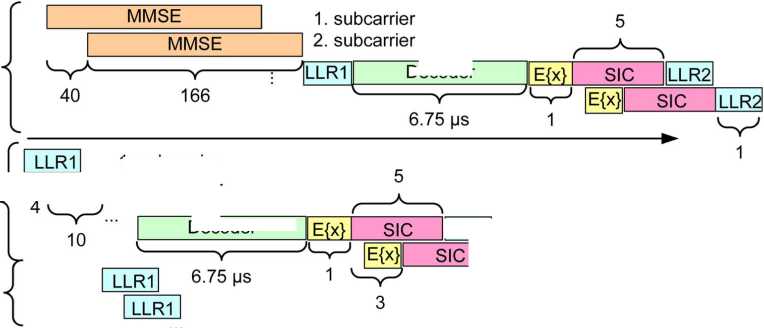
Fig. 15. The timing and latencies in the SIC receiver with 4× 4 16-QAM.
_______ 1. subcarrier
LLR1∣ 2. subcarrier
Decoder
∣∣LLR2j 1. subcarrier
I LLR2∣ 2∙ subcarrier
TABLE VIII
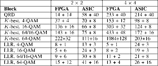
Latency of the K-Best LSD Receiver

TABLE IX
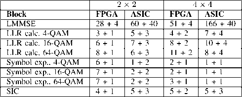
Latencies of the LMMSE and SIC Receivers

total latency estimate and it is calculated from the results given
in [33], where the decoding rate is 711 Mb/s. The turbo decoder
limits pipelining in the SIC receiver in a way that all the subcar-
riers have to be decoded before moving to the symbol expecta-
tion calculation. The LLR1 block includes detection and LLR
calculation and it can start to process the next OFDM symbol
while the second layer in the previous symbol is being calcu-
lated.
The LLR calculation block produces QN bit LLRs in the
given latency period. Symbol expectations for a subcarrier are
calculated in the given period. The latencies in the ASIC im-
plementation were set to achieve the detection rates needed to
process the data according LTE time frames in a 20-MHz band-
width. 20 MHz is the maximum bandwidth in LTE, but lower
bandwidths, such as the 5 MHz bandwidth used in the simula-
tions, are also possible.
In the LTE specifications, a 0.5-ms slot has been allocated
for 7 or 6 (depending on the length of the cyclic prefix length)
OFDM symbols [21]. In the SIC receiver, seven OFDM sym-
bols are processed in 0.46 ms when the MMSE weights are
not calculated. Including the MMSE weight matrix calculation
when the channel realization changes, averages the processing
time to 0.5 ms. The slot time translates to detection rate with
7QTVP∕(0.5 ms). The required detection rates in the 20-MHz
bandwidth and a 2 × 2 antenna system are 68 Mb/s for QPSK,
136 Mb/s for 16-QAM, and 203 Mb/s for 64-QAM. The re-
quired rates are doubled in the 4 × 4 antenna case. The LMMSE
receiver is fast enough to be used in all antenna and modulation
cases. The SIC receiver does not achieve the required rates in
the 4 × 4 case on FPGA but in other cases the requirements are
met. The Æ-best LSD meets the requirements only in the 2 × 2
QPSK case on FPGA with the used technology. However, the
Jf-best LSD could be used for a 5-MHz bandwidth. The ASIC
implementations meet the requirements except with the 4 × 4
64-QAM and list size 16 in the 4 × 4 16-QAM case.
V. Discussion
The theoretical complexities of the algorithms were pre-
sented. The complexity of the A-bcsl algorithm is close to that
of the SIC algorithm with low order modulations but the differ-
ence is greater with higher modulations. The implementation
results in Section IV support the theoretical results in Table III:
the receivers have similar complexities with low order modula-
tions but the complexity of the K-best LSD increases with the
modulation order. The LMMSE calculation was implemented
as a direct matrix inversion in the 2×2 case which made the
SIC less complex even with low order modulations.
The performance-complexity tradeoff of the ASIC imple-
mentations in a 2×2 16-QAM in a correlated channel is
summarized in Table X and in the 4×4 16-QAM case in
Table XI. The detection rates of the receivers are the same.
Even though the detection rate of the LMMSE receiver is high,
the performance degradation in terms of reliable transmission
throughput is considerable in particular at the cell edge, where
the available SNR is often low. Thus, the term goodput is de-
fined to be the minimum of the hardware detection rate times the
1/2 code rate and the reliable transmission throughput (which,
on the other hand, was defined in Section III as transmission
rate of information bits over the 20-MHz bandwidth times
More intriguing information
1. Proceedings of the Fourth International Workshop on Epigenetic Robotics2. Endogenous Heterogeneity in Strategic Models: Symmetry-breaking via Strategic Substitutes and Nonconcavities
3. Income Taxation when Markets are Incomplete
4. EDUCATIONAL ACTIVITIES IN TENNESSEE ON WATER USE AND CONTROL - AGRICULTURAL PHASES
5. Synthesis and biological activity of α-galactosyl ceramide KRN7000 and galactosyl (α1→2) galactosyl ceramide
6. The name is absent
7. Exchange Rate Uncertainty and Trade Growth - A Comparison of Linear and Nonlinear (Forecasting) Models
8. FDI Implications of Recent European Court of Justice Decision on Corporation Tax Matters
9. The name is absent
10. The Demand for Specialty-Crop Insurance: Adverse Selection and Moral Hazard