10
EURASIP Journal on Applied Signal Processing
b11(r) b21 (r/i) b22(r)

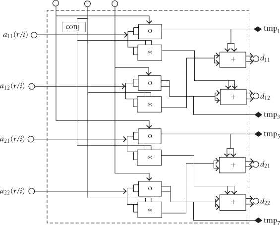
Figure 6: The simplified parallel VLSI RTL layout of the M(A, B) processing unit.

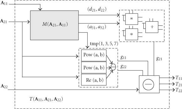
Figure 7: The VLSI RTL architecture layout of the T(A11,A21,A22) block.
transform T(A11,A21,A22)ofthe(4× 4) Hermitian matrix is
given by Figure 7. The output ports of the T(A11, A21, A22)
include the independent elements {t11, t21, t22}.
We can further simplify the top-level RTL schematic by
extracting the commonality of the M and T module designs
as in Figure 8 to eliminate the extra individual M module.
Thus, the results of C11, C12, and C21 are generated together
from the second T module. Compared with the design in
Figure 5, the architecture demonstrates better parallelism
and reduced redundancy. The data path is much better bal-
anced and facilitates the pipelining in multiple subcarriers
for high-speed design.
If we use a standard computing architecture of the par-
titioned (4 × 4) matrix inverse, we need 308 real multi-
plications before dependency optimization (DO). With a
straightforward DO, the complexity is still 244 real multipli-
cations. Traditionally, a complex multiplication is given by
“c = cr + jci = (ar + jai) * (br + jbi) = (arbr - aibi)+ j(arbi +
ai br).” This has 4 real multiplications (RM) and 2 real ad-
ditions (RA). By rearranging the computation order, we can
reduce the number of real multiplications as (1) p1 = arbr,
p2 = aibi, s1 = ar + ai, s2 = br + bi; (2) cr = p1 - p2,
d = (p1 + p2), s = s1s2; (3) ci = s - d. This requires 3
real multiplications and 5 real additions in three steps. A sin-
gle T transform needs only 38 RMs for a (4 × 4) Hermitian
matrix. Thus, there are 90 RMs to compute the F(i)-1 with
the optimized Hermitian architecture. This is only less than
1/3 of the real multiplications for a traditional architecture as
shown in Table 2. Note that the critical data path is also dra-
matically shortened with better modularity and pipelining.
More intriguing information
1. The name is absent2. Developing vocational practice in the jewelry sector through the incubation of a new ‘project-object’
3. Natural hazard mitigation in Southern California
4. Factores de alteração da composição da Despesa Pública: o caso norte-americano
5. New urban settlements in Belarus: some trends and changes
6. Økonomisk teorihistorie - Overflødig information eller brugbar ballast?
7. The name is absent
8. THE DIGITAL DIVIDE: COMPUTER USE, BASIC SKILLS AND EMPLOYMENT
9. Fiscal Policy Rules in Practice
10. The problem of anglophone squint