Yuanbin Guo et al.

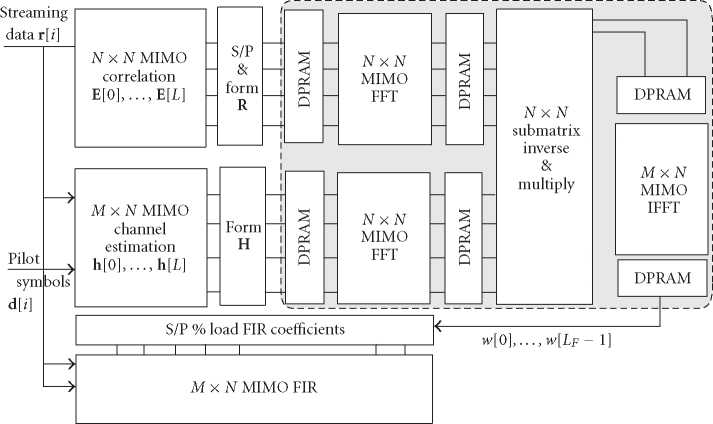
Figure 2: The block diagram of the VLSI architecture of the FFT-based MIMO equalizer.
(M × N ) MIMO-FIR block for filtering. To reflect the cor-
rect timing, the correlation and channel estimation mod-
ules at the front end will work in a throughput mode on
the streaming input samples. The FFT-inverse-IFFT modules
in the dotted line block construct the postprocessing of the
tap solver. They are suitable to work in a block mode us-
ing dual-port RAM blocks as interface between blocks. The
MIMO-FIR filtering will also work in throughput mode on
the buffered streaming input data.
4. VLSI-LEVEL COMPLEXITY OPTIMIZATION
4.1. Hermitian optimization
In this section, more emphasis is given to the VLSI-oriented
implementation aspects. For QPSK and QAM modulation
schemes, all the numerical computations in the algorithm are
associated with complex numbers. However, the complexity
in the hardware is reflected by the number of real multipli-
cations, additions, and divisions, and so forth. It is more ac-
curate to clarify the complexity for different types of com-
putations. For example, a general “complex (a) × complex
(b)” numerical computation has 4 real multiplications and 2
real additions, but a “complex (a) × conjugate (a)” reduces
to only 2 real multiplications and 1 real addition. By defin-
ing Fn1,n2 [0 : LF - 1] as the element-wise FFT vector of the
covariance block-vector for n1, n2 ∈ [1,N], we show that the
element-wise FFT of the circulant covariance vectors admits
a Hermitian structure. This leads to the following lemmas for
complexity reduction.
Lemma 1 (Hermitian). Fn1,n2 = conj(Fn2,n1), where the vector
is formed from the covariance element vector between antennas
n1 and n2. Fn2,n1 is redundant for n2 <n1.
Lemma 2 (Hermitian complexity). The computation of
Fn1,n1 can be reduced to only L/LF of the full DFT module.
Proof. For the Rx antennas n1, n2, it can be shown that the el-
ements in the circulant column have the following relations,
where NB is the covariance time-average window length:
NB-1
e(^n2(0) = (Egn 1(0))* = Σ rn 1(i)rn2(i)*,
i=0
NB-1
= rn1(i)rn2(i+l)*,
i=0 (12)
NB-1
= rn2(i)rn1(i+l)*,
i=0
Eg n 2( l ) = (En2), n 1 ( LF — l )) *
Egn2 (LF - l) = (En?,n 1(l))*
Eg n 2 ( l ) = ( E⅛). n 1 ( LF - l )) * = 0 otherwise ∙
Using the features of the FFT, it can be proven that
the element-wise FFT results have the relation that Fn1,n2 =
(Fn2,n1 )* . The submatrix formed by the ith entry of Fn1,n2
is an (N × N) Hermitian symmetric matrix as F(i) =
(Fn1,n2(i))N×N = F(i)H.
Thus, instead of having N × N complex FFT computa-
tions, we only need to compute the element-wise FFT for the
lower triangle matrix. The number of FFTs in the element-
wise FFT is reduced from N2 to (N2 + N)/2. Moreover, the
element-wise FFT coefficients of the diagonal elements are
all real numbers. This leads to the design of the reduced-state
MIMO-FFT blocks. □
4.2. Reduced-state FFT
Because the FFT algorithm applies the features of the rota-
tion coefficients, the application of the Hermitian feature to
FFT is not straightforward. Here, we derive the VLSI-level
optimization for the reduced-state FFT with pruning op-
erations based on the standard radix-2 decimation-in-time
(DIT) FFT algorithm. Notice that in the standard butterfly
More intriguing information
1. Road pricing and (re)location decisions households2. Spectral density bandwith choice and prewightening in the estimation of heteroskadasticity and autocorrelation consistent covariance matrices in panel data models
3. The name is absent
4. Large-N and Large-T Properties of Panel Data Estimators and the Hausman Test
5. Midwest prospects and the new economy
6. HOW WILL PRODUCTION, MARKETING, AND CONSUMPTION BE COORDINATED? FROM A FARM ORGANIZATION VIEWPOINT
7. National curriculum assessment: how to make it better
8. Fertility in Developing Countries
9. How does an infant acquire the ability of joint attention?: A Constructive Approach
10. APPLICATIONS OF DUALITY THEORY TO AGRICULTURE