75
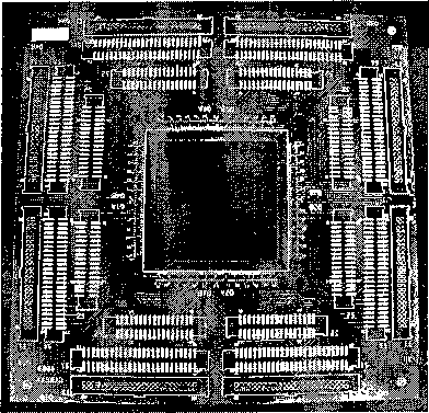
(a) SLM circuit board
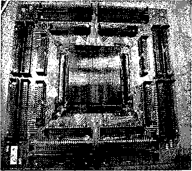
(b) SLM board (with components)
Figure B.7 : (a) The SLM circuit board has a 34 mm × 34 mm square hole surrounded
by 1040 gold bond fingers, designed to mount and to wire-bond the SLM chip, (b)
Besides the SLM chip, the SLM circuit board also has 24 cable connectors which
receives voltage-amplified control signals from the line driver circuit.
B.5 SLM board
The SLM board is the interface between the SLM control circuit and the SLM chip,
designed to fit the constraints in the wire-bonding procedures and to move around
easily while conducting experiments.
As shown in Figure B.7, the SLM board, 4.5” × 4.5” in size and 40-mil thick, has
a 34 mm × 34 mm square hole in the middle, surrounded by 260 gold bond fingers on
each side of the square. Each bond fingers are 5 mils × 20 mils and are electroplated
with 60 microinches of soft bondable gold. Four 4-40 screw holes at the four corners
of the square hole are useful for fixing the board in position during wire-bonding,
and for an add-on transparent plastic case for chip protection. The distance from
one side of the square hole to the edge of the board is around 1.5”, which must be
More intriguing information
1. Empirical Calibration of a Least-Cost Conservation Reserve Program2. Business Cycle Dynamics of a New Keynesian Overlapping Generations Model with Progressive Income Taxation
3. Wirkt eine Preisregulierung nur auf den Preis?: Anmerkungen zu den Wirkungen einer Preisregulierung auf das Werbevolumen
4. Optimal Rent Extraction in Pre-Industrial England and France – Default Risk and Monitoring Costs
5. WP 1 - The first part-time economy in the world. Does it work?
6. Rural-Urban Economic Disparities among China’s Elderly
7. Getting the practical teaching element right: A guide for literacy, numeracy and ESOL teacher educators
8. Literary criticism as such can perhaps be called the art of rereading.
9. Revisiting The Bell Curve Debate Regarding the Effects of Cognitive Ability on Wages
10. Firm Creation, Firm Evolution and Clusters in Chile’s Dynamic Wine Sector: Evidence from the Colchagua and Casablanca Regions